
A step-by-step primer for international buyers
1. Engineering & Preparation
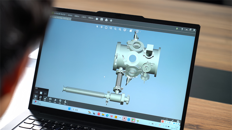
1.1 Design package
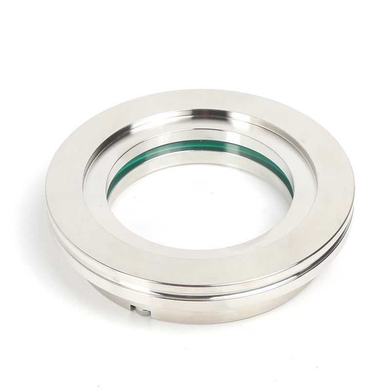
- Geometry: define internal layout, pump, gauge and viewport ports, electrode/target positions.
- Vacuum spec: set ultimate pressure, leak rate, proof pressure; choose alloy, weld method, seal type accordingly.
- Documentation: detail drawings, general assembly, weld-sequence plan, full GD&T.
1.2 Materials & consumables
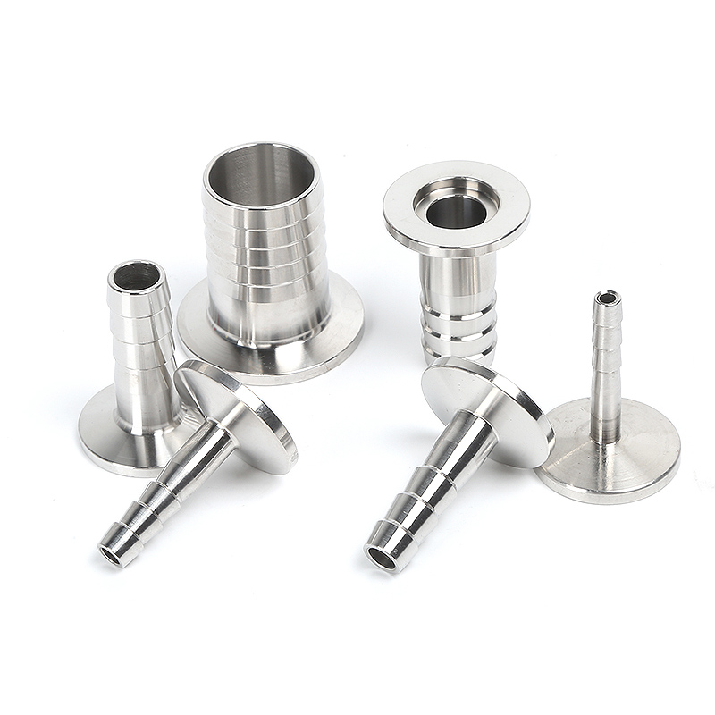
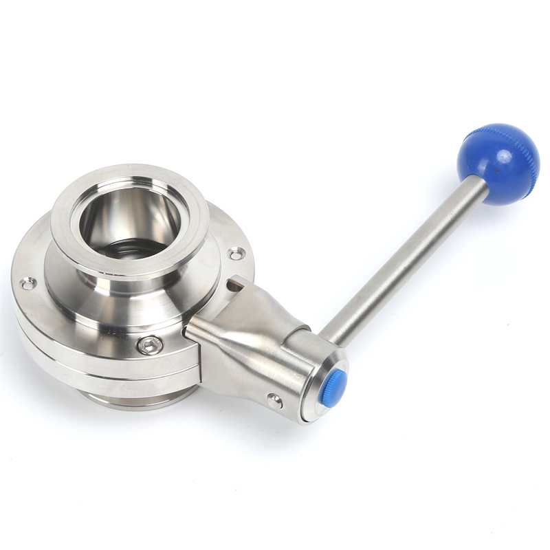
- Alloys: 304L/316L austenitic stainless (low-carbon, low out-gassing); Al- or Ti-alloys on request.
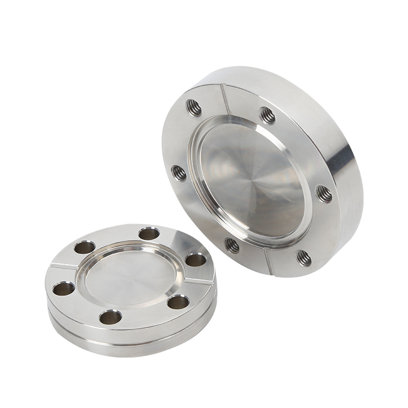
- Consumables: matching filler wire, vacuum-grade seals, CF/KF hardware.
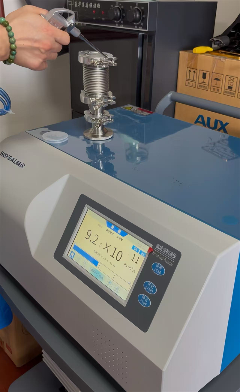
- Metrology: helium mass-spectrometer leak detector, surface roughness gauge, CMM.
2. Material processing
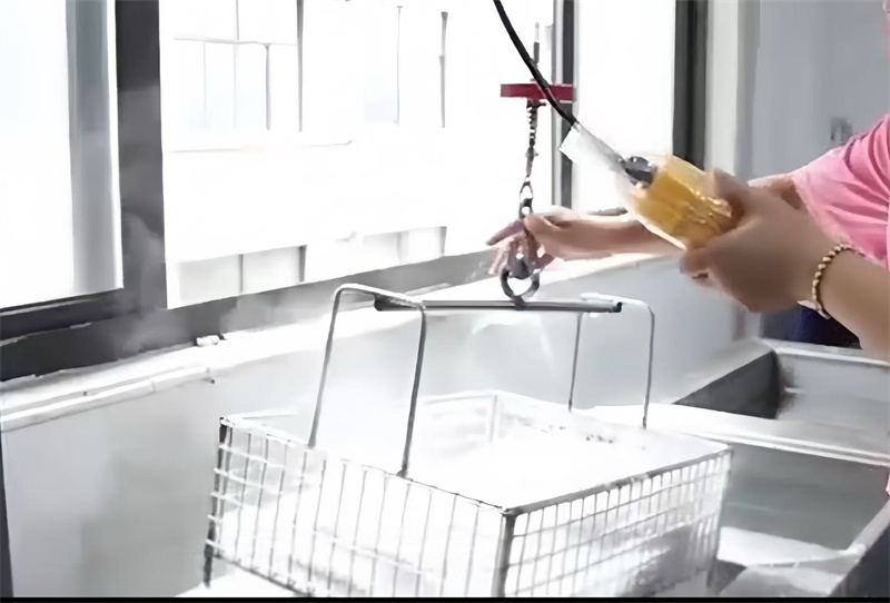
2.1 Pre-treatment
- Degrease: alkali or ultrasonic bath to remove rolling oils.
- Pickle & passivate: strip oxide/scale, restore Cr-oxide film.
- Protection: gloves or peel film during machining.
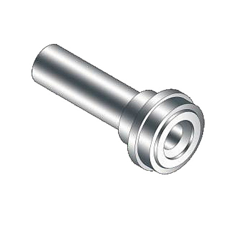
2.2 Cutting & forming
- Cut: plasma, laser or water-jet.
- Roll: cylinders on plate rolls; rectangular shells brake-formed.
- Machine: finish seal grooves, threaded ports to Ra ≤ 0.8 µm.
- Hole-making: CNC-cut windows, pump ports; break all edges.
3. Fit-up & welding
3.1 Tack assembly
- Locate with minimal tack welds; sequence chosen to balance shrinkage.
3.2 Welding
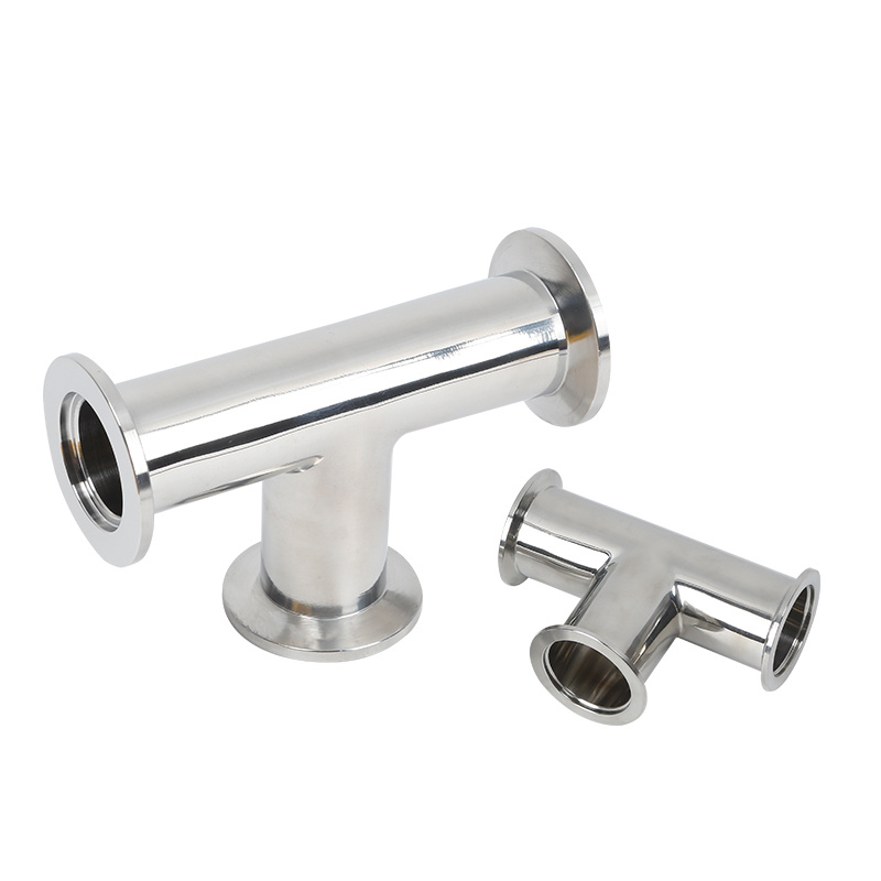
- Process: GTAW (TIG) as default; electron-beam for high-purity joints.
- Acceptance: zero porosity, full penetration, smooth internal bead; single-side welds often back-shielded for “double-sided” profile.
- Critical seams 100 % He-leak tested in situ.
4. Post-weld operations
4.1 Stress relief
- Furnace or local PWHT 450–650 °C; large parts may use vibratory stress relief.
4.2 Final cleaning
- Re-pickle weld zones; ultrasonic rinse → DI water → hot-air dry; certified to ≤ 1 mg/m² residual organics.
5. Quality verification
- Dimensional & visual: chamber length, port spacing, flange flatness ≤ 0.1 mm/100 mm.
- Vacuum: integral leak rate ≤ 1 × 10⁻⁹ Pa·m³/s (or client class).
- Pump-down: reach specified ultimate within published curve.
- Mechanical: hydrostatic or pneumatic proof test at 1.3 × design pressure.
6. Finishing & dispatch
- Surface: glass-bead, satin polish or electropolish (Ra ≤ 0.4 µm) to cut gas load.
- Protection: PVC film + desiccant bag, shock-mounted crate.
- Release to stock or direct integration with pumps, valves and deposition sources.
With every stage traceable to ISO 9001 and EN 13980 (ATEX) where required, our chambers arrive ready for immediate high-vacuum duty—anywhere on the globe.
 Hot News
2025-08-01
2025-07-24
2025-11-19
2025-12-25
2026-01-31
Copyright © Wenzhou QiMing Stainless Co., Ltd. All Rights Reserved - Privacy Policy - Blog